Build Steps
This is a draft version of the Delta Flyer build-manual and is not the final manual.
In this document I'm going to walk you through building the Flyer in rough steps. Please be aware that you would need some experience building printers to follow these instructions.
First of all, you will need some tools:.
- Soldering Iron or a heatset-press to insert heatsets into the printed parts.
- Epoxy and CA glue
- 2 and 3mm hex screwdrivers
- PC with microSD card reader
ℹ️ Printed Parts
If you havent already printed your parts, I have a general printing guide that might be for you.
ℹ️ Carriages needs extra care!
The carriages needs to be printed in a dark, non-translucent filament for the optical endstops to work, you can do a filament swap to make just the little horn on them in a dark filament if you want.
⚠️ Important
This has been written from memory, so please let me know if I've missed something.
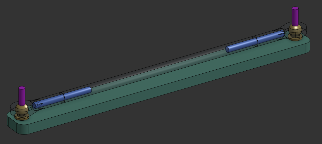
Glue the arms together using the M3x30 threaded rods between the joints and the 100mm rods on the printed jig. Use 2xM3x20 in the jig to allign everyhing. Keep the joints oriented identically on each end.
⚠️ Important
Be extra carefull when gluing these together, do them one at a time on a single printed jig for the best result.
ℹ️ Printing parts
There are two different sets of carbon rods in the kit, 100mm long is for the joints that are included, 105mm is for making arms using the optional MPJets
Prepare all printed parts by removing all the built-in supports from:
- Top_Frame(middle) (light blue piece)
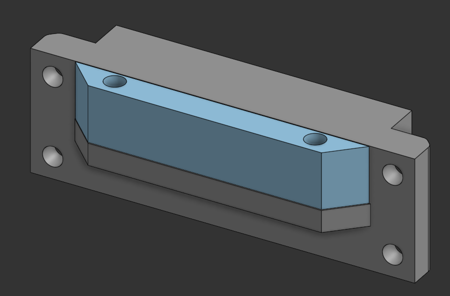
- Top_Frame_A and B (gray piece)
- Top_Frame_C (gray piece)
- Carriage (gray piece)
⚠️ Important
Ensure all support material is completely removed before assembly to prevent fitment issues.
Insert headsets into the following pieces:
- Updated_Top_Frame_A.stl
- Updated_Top_Frame_B.stl
- Updated_Top_Frame_C.stl
- Updated_Top_Frame_Middle.stl
- 2 x Updated_Top_Frame_side_with_support.stl
- Updated_Bottom_Frame_A.stl
- Updated_Bottom_Frame_B.stl
- Updated_Bottom_Frame_C.stl
- 2 x Updated_Bottom_Middle.stl
- Updated_Bottom_Frame_Center.stl
- Effector.stl
- TR6_Hotend_Mount_LDO.stl
- 3 x Tensioner.stl
- Top_Cover_A.stl
- Top_Cover_B.stl
- Top_Cover_C.stl
- Handle.stl
- 2 x Hinge.stl
ℹ️ Tip
Press headsets in firmly and ensure they are seated flush with the printed part surface.
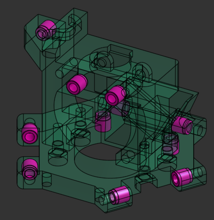
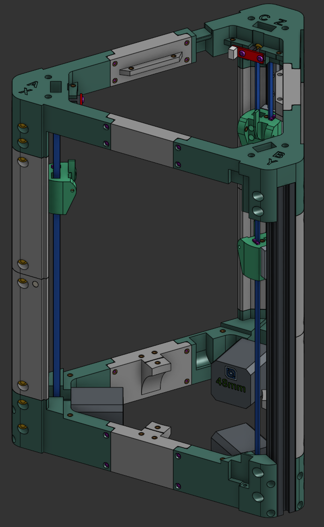
Start by assembling each of the 3 bottom corners.
Insert the F695 bearing into the lower frame corner. Put the GT2 pulley on the motor with the setscrew facing towards the motor. Dont tension the setscrew yet. Attach the motor to the frame corner using 4x M3x30 socket head screws. Cable notch facing either left or right, not up or down.
⚠️ Important
Ensure the pulley setscrew is positioned towards the motor for proper belt alignment.
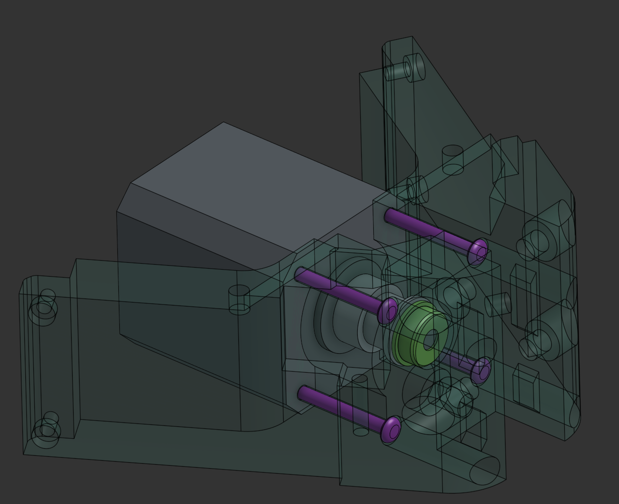
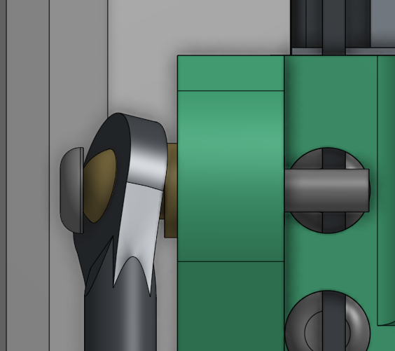
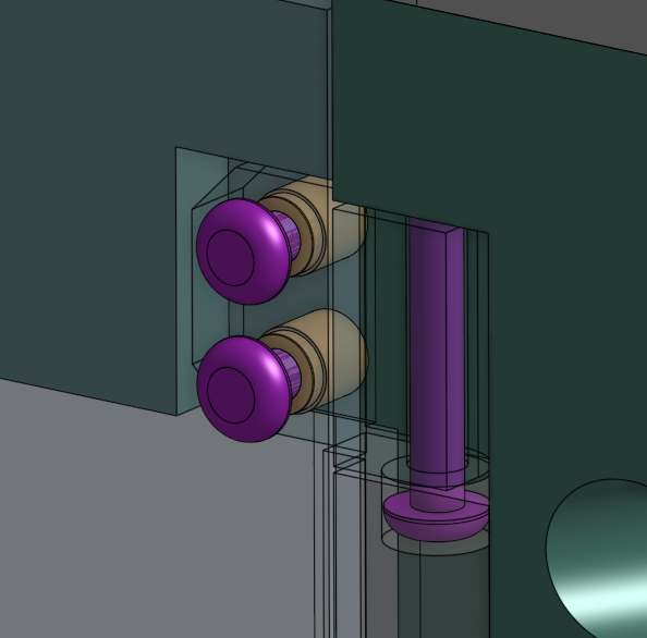
On the top frame corners, attach the GT2 idler with a M5x16 screw.
Then attach the optical endstop with the black protrusion facing toward the M5 screw head using 2x M3x10 screws.
ℹ️ Note
The endstop orientation is critical for proper homing functionality.
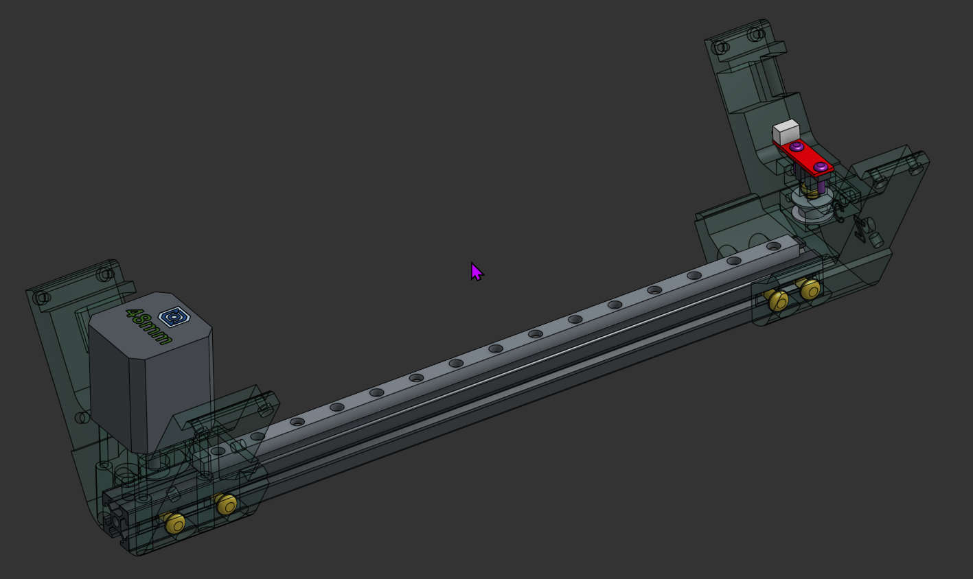
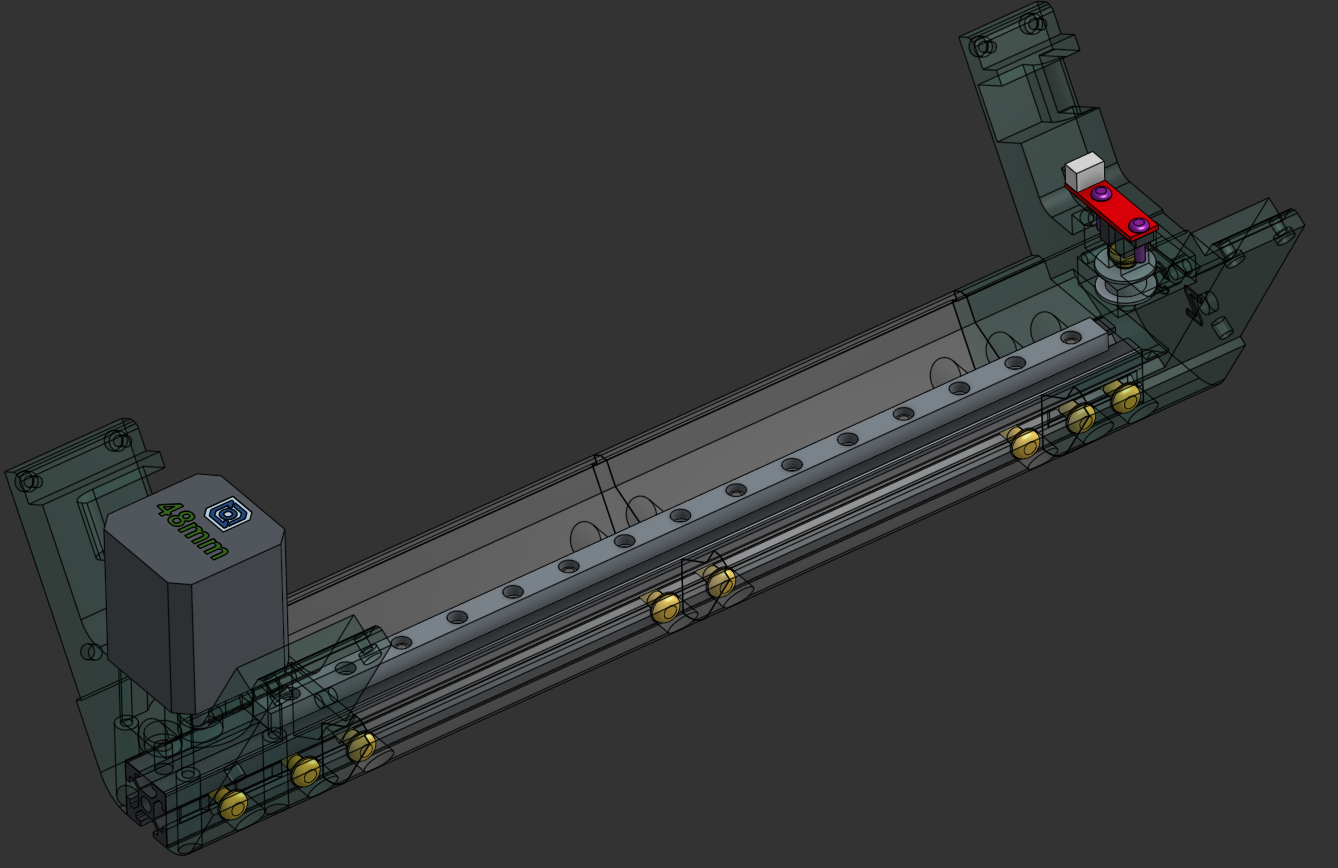
Attach the 2020 extrusion to the top frame corner using 4x M5x10 screws and T-nuts.
Then attach the MGN9 rail using 5x M3x8 screws and T-nuts.
Finally, loosely attach the bottom corner piece to the extrusion using 4x M5x10 screws and T-nuts.
ℹ️ Note
The bottom corners are all different and have labels matching the top corners. If you have the bottom corners with no labels, pair the bottom corners to the top by looking at the external heatsets, they should match bottom to top.
⚠️ Important
Make sure the carriages dont slide off the rail when moving it around. Keep the rubber stoppers in for as long as possible.
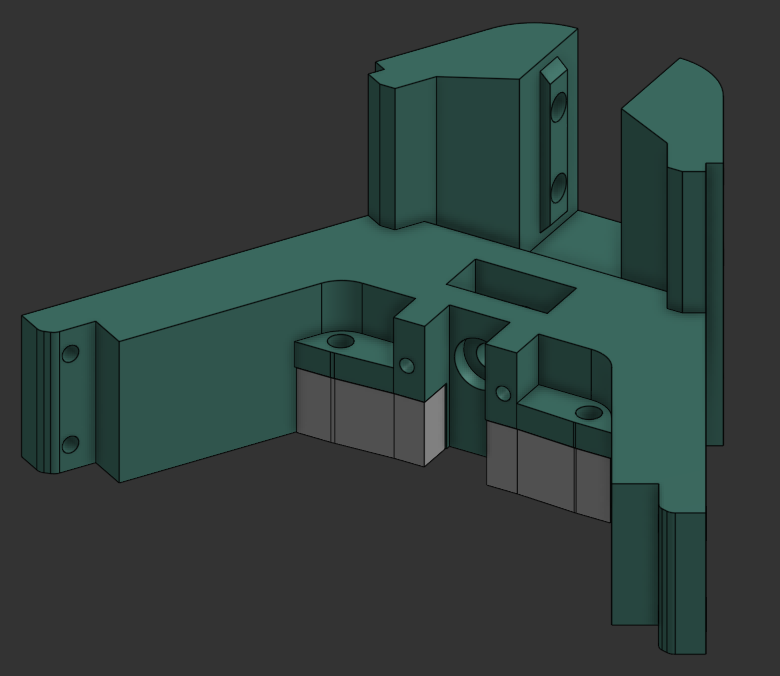
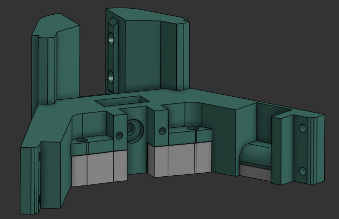
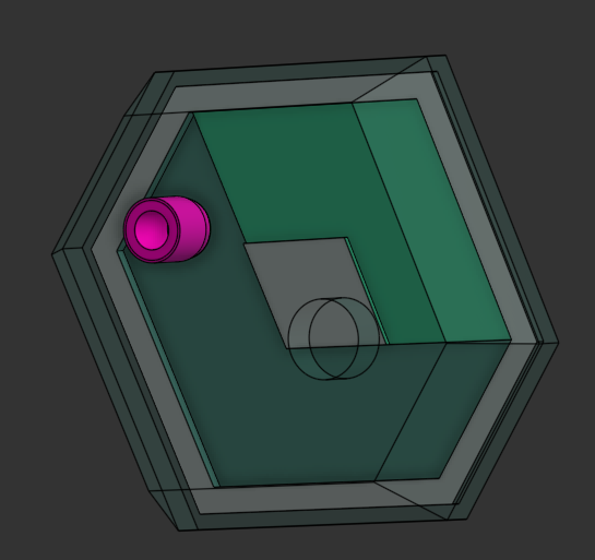
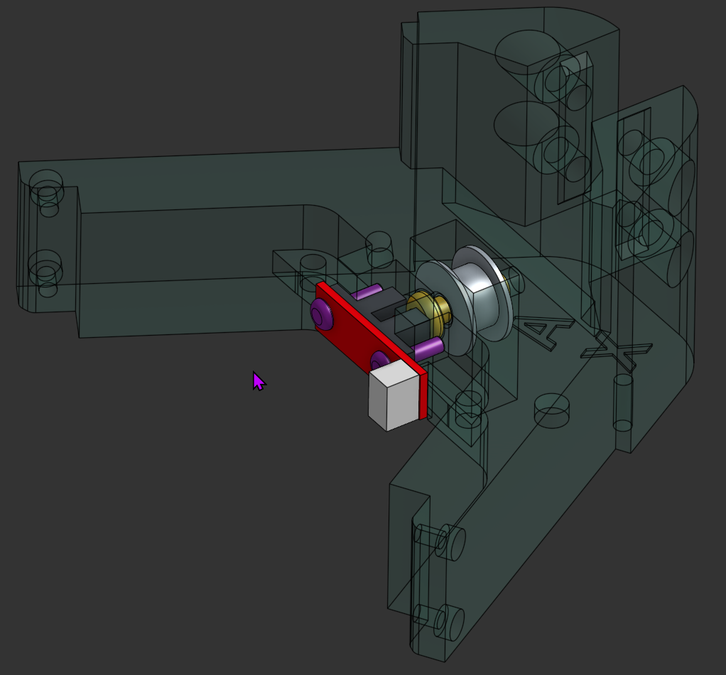
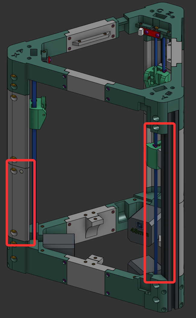
Attach the 4 corner panel pieces to each upright using 2x M5x10 on each panel, but do not attach the two front corner panels on the "B" corner - these are attached later after the door hinges.
ℹ️ Note
The front lower panel cover on the "A" upright has a hole for a magnet.
ℹ️ Note
Note the position of the cover with the hole for the magnet and that we dont put the front covers where the door goes yet. (in red)
💡 Tip
Now you can make sure all the upright assemblies are identical in length between the top and bottom frame pieces.
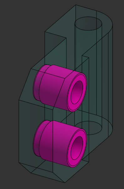
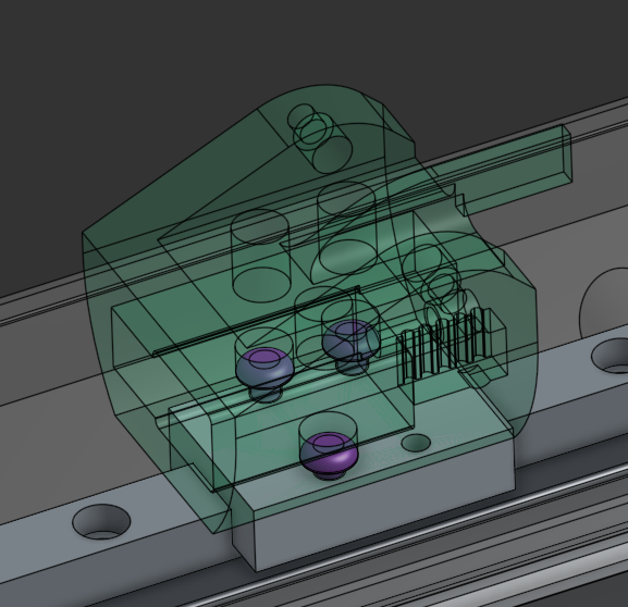
Attach the carriages to the MGN9 rails using 3x M3x6 screws.
⚠️ Belt Length
Cut each belt to 690mm
Using the Apex clips, fasten the belt to the tensioner. Put the tensioner into the carriage (apex clip down) and route the belt down around the pulley, back up through the carriage, around the top idler and back into the carriage, attached with another apex clip.
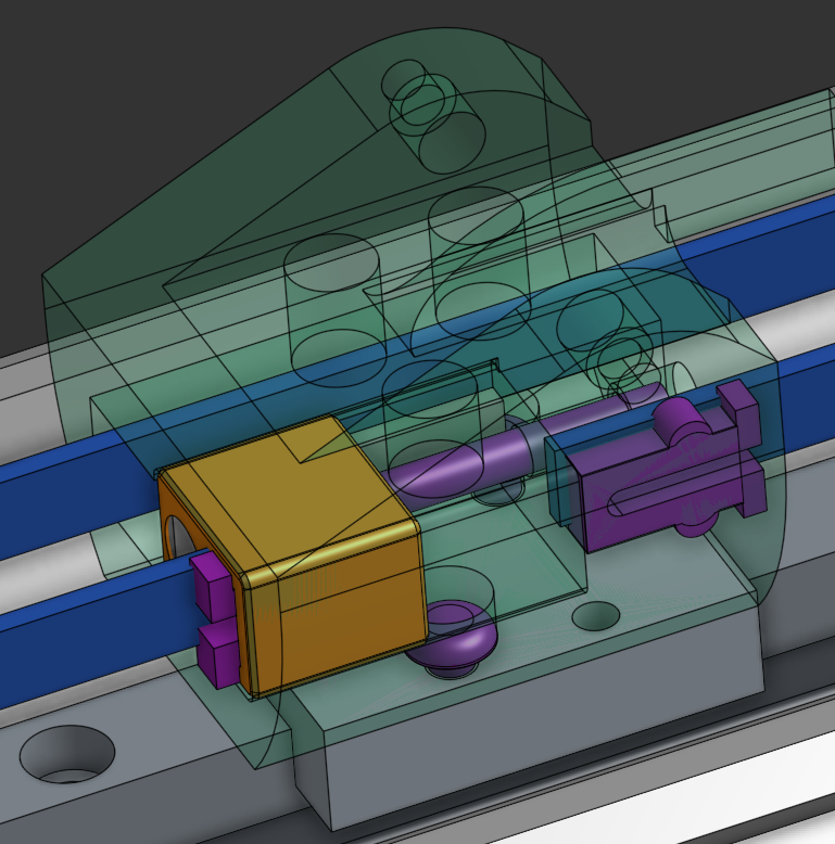
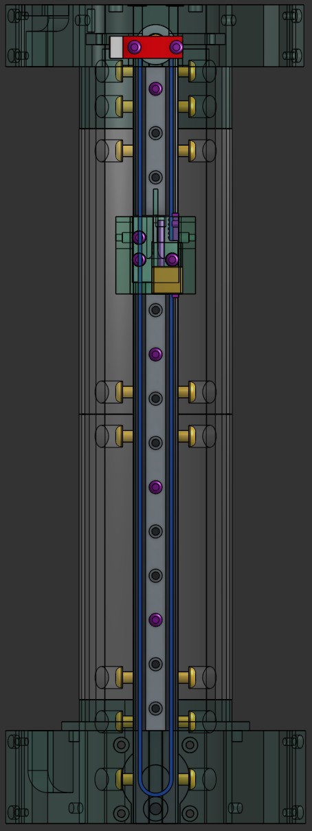
Use a M3x30 screw to tension the belt to the carriage. You can now tighten the grub-screws on the pulleys, making sure its all alligned with the belt.
💡 Tip
Don't over-tension the belts initially - you can fine-tune tension after the printer is assembled.
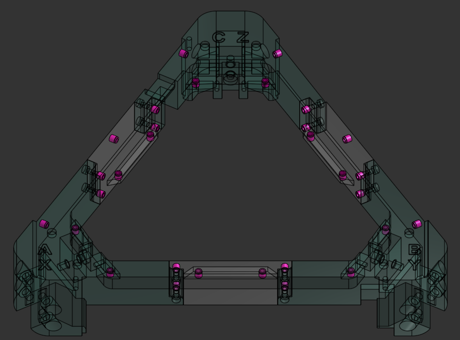
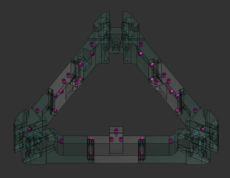
Bolt the frame together using 24x M3x12 screws Remember to have the middle frame pieces without heatsets on the outside towards the front and the top middle frame pieces with the panel-ledge on the lower part.
⚠️ Note
Make sure you note the positions of the frame spacers, two of them dont have a heatset on the front face, those are for the front of the printer.
Add the small sticky feet to the bottom of the frame.
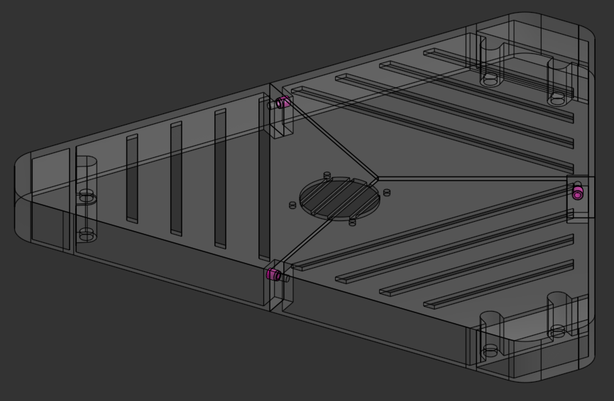
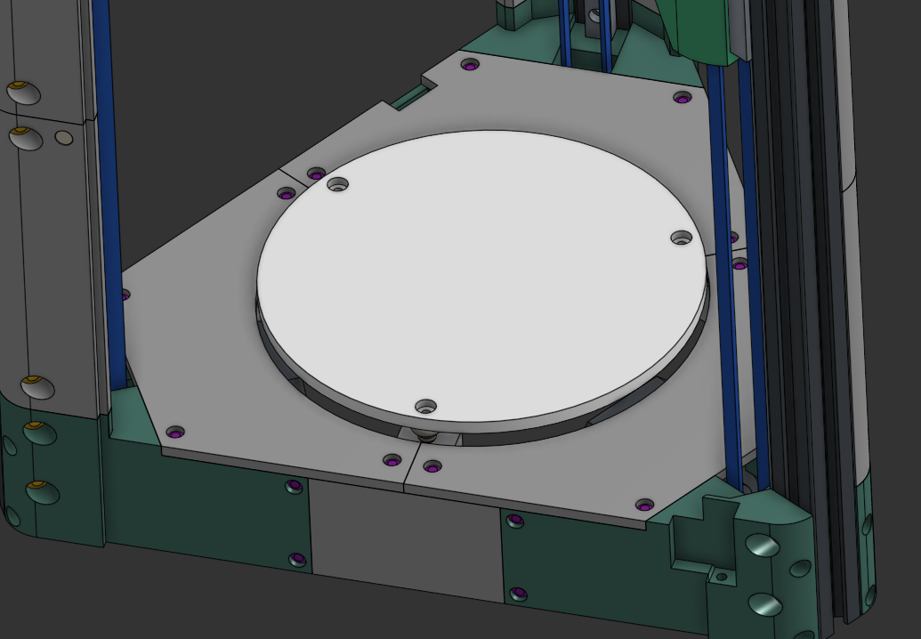
Attach the heated bed to the frame using 3x M3x16 screws and 3x M4 thumbnuts as spacers between the bed and the frame.
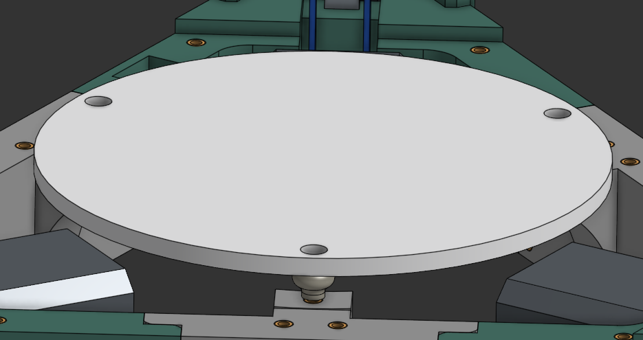
⚠️ Note
The bed arrive pre-assembled - plug and play!
Attach the 3 motor covers using 12x M3x6 screws. Note that the one with the notch goes on the back "C" corner.
Attach the top electronics panels using 12x M3x6 screws. These are marked, text goes up.
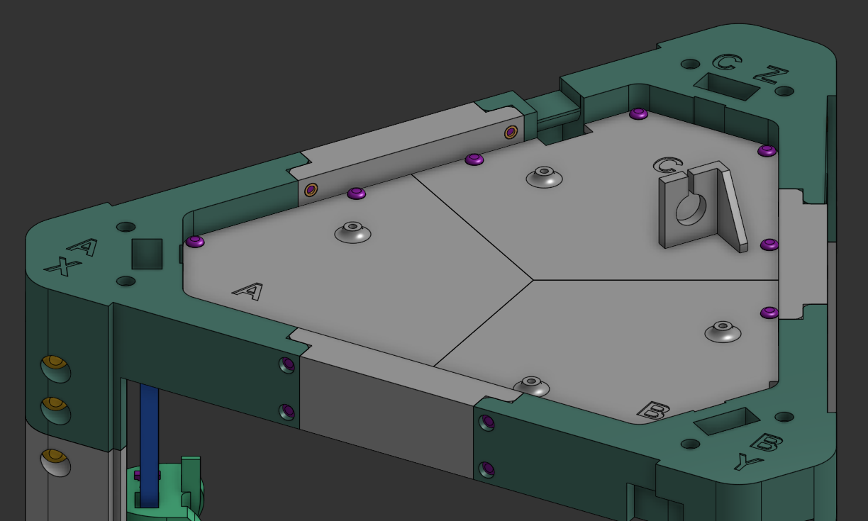
ℹ️ Tip
Check the panel markings carefully to ensure correct orientation.
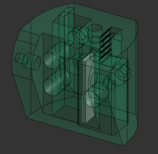
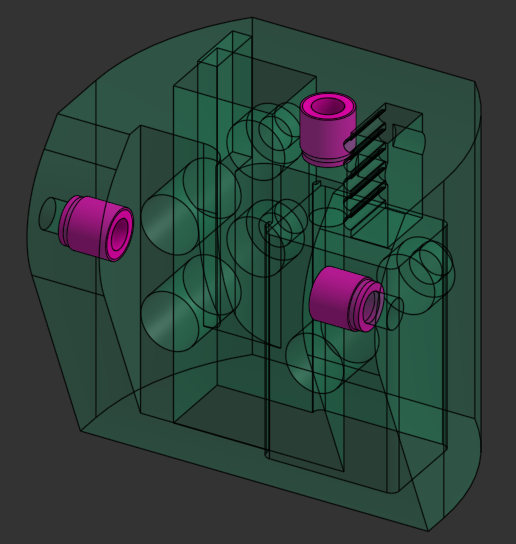
Attach the TR6_hotend_mount to the Effector using 4x M3x8 screws.
⚠️ Note
You are screwing into plastic, dont over-tighten these.
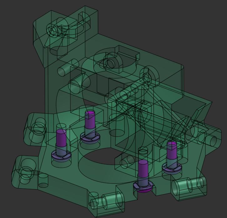
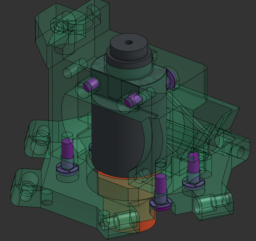
Attach the TR6 hotend to the TR6_hotend_mount using 2x M3x16 screws.
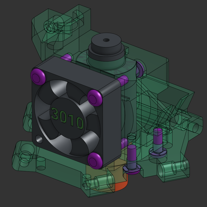
Attach the 3010 hotend fan using 3x M3x16 screws. Make sure the sticker on the fan is facing intowards the hotend.
Route the hotend wires out the left side of the effector, grab the 3010 fan wires and route them all through the cable relief hole on the 5015 fan mount side and attach the 5015 fan using a M3x20 screw. Make sure you get the 5015 wire in that hole as well.
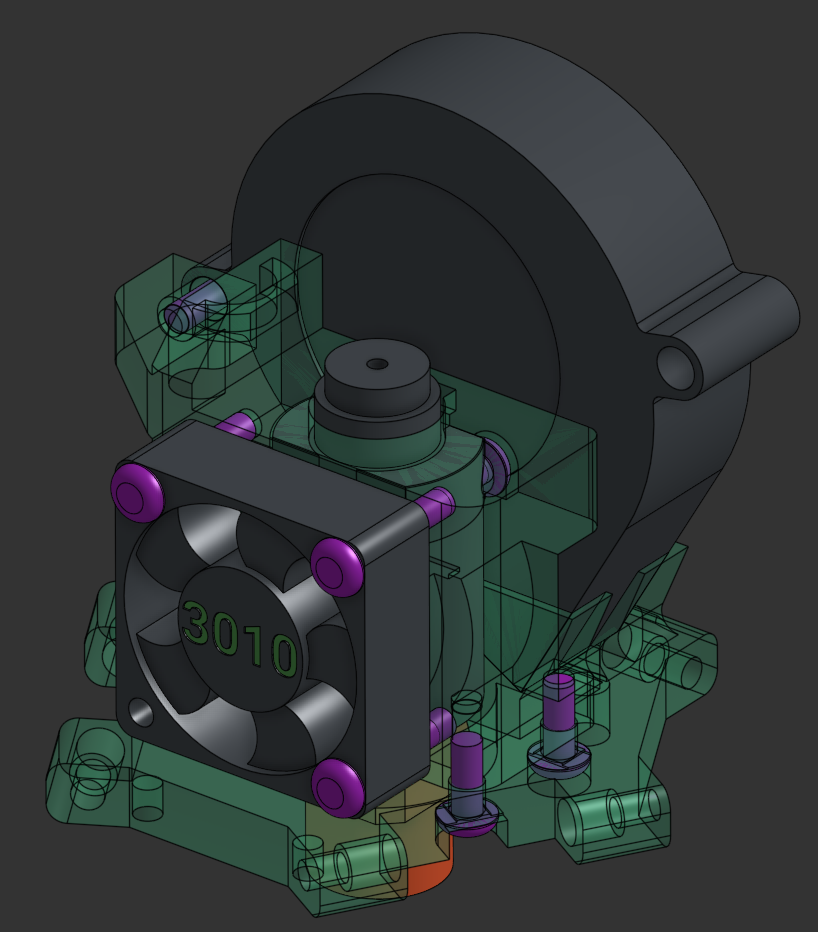
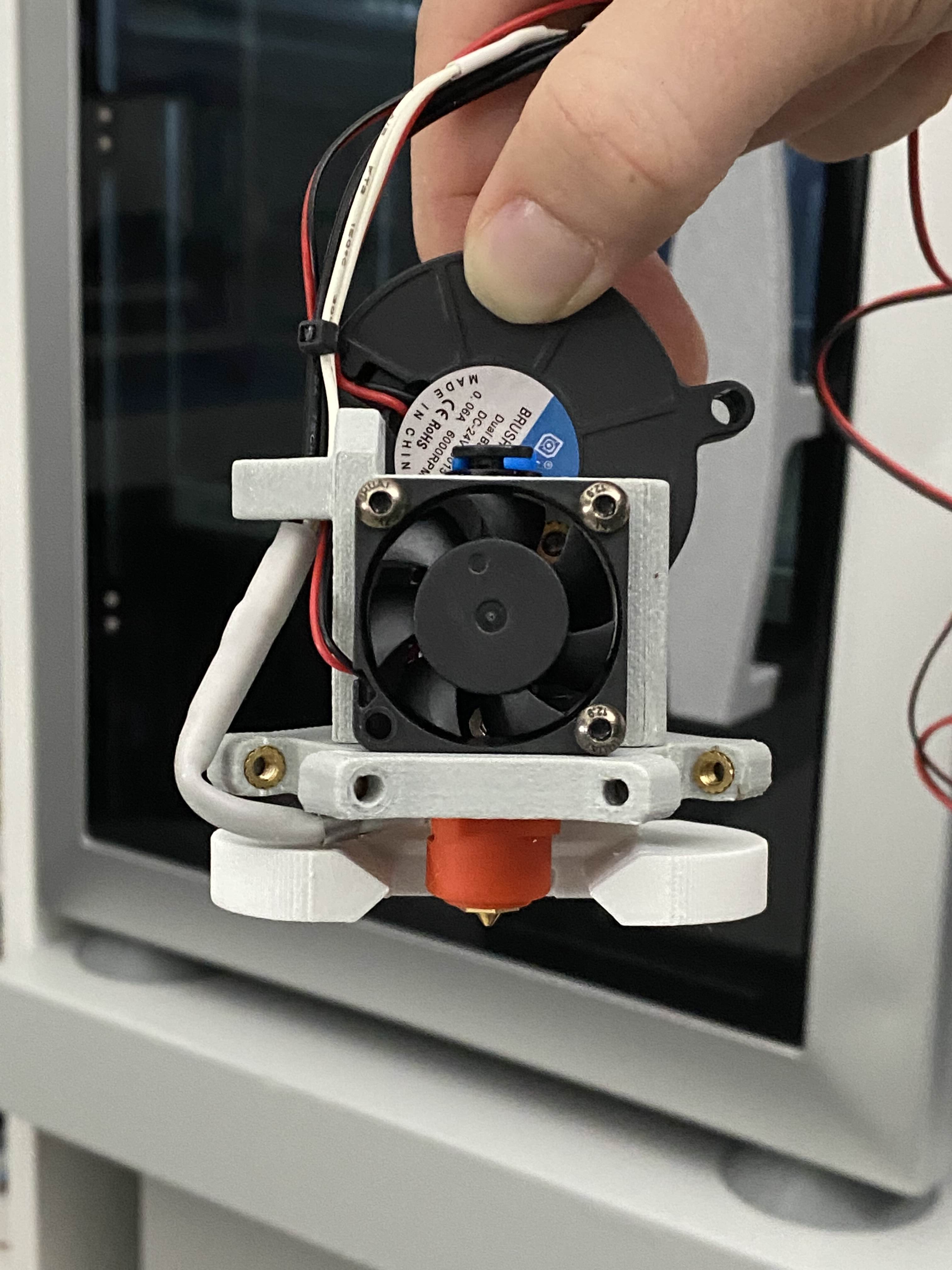
(Thank you to Mitsubishi Makes for this image)
Bolt the Trihorn duct to the bottom of the effector using 2x M3x16 screws.
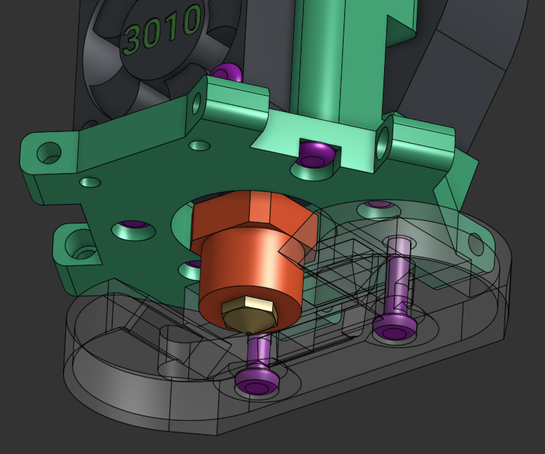
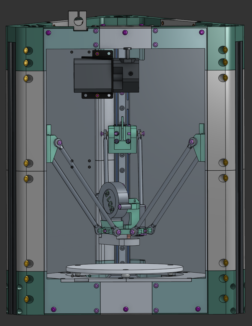
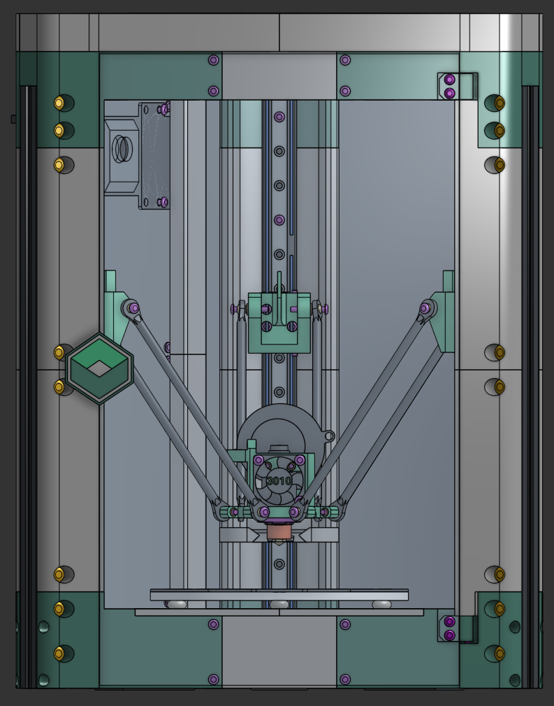
Bolt the effector to the carriages using the arms and 12x M3x20 screws in the orientation showed here.
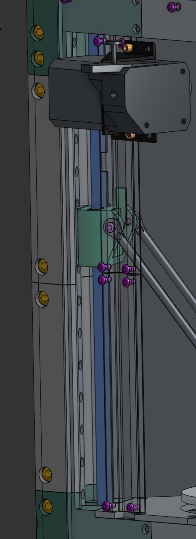
Attach the back left panel using 6x M3x10 screws, then attach the BMG extruder to it using 2x M3x10 screws and heat inserts as nuts. Note that you'll need to cut off a part of the BMG mount to clear a screw later on.
⚠️ Note
No need to over-tighten the bolts on the panels, you risk cracking the panel.
💡 Tip
This is a good time to cut and install the PTFE tube to the proper length. I have found 31cm to be a good length. Install the PTFE in the extruder with the little locking clip before mounting the extruder to the panel.
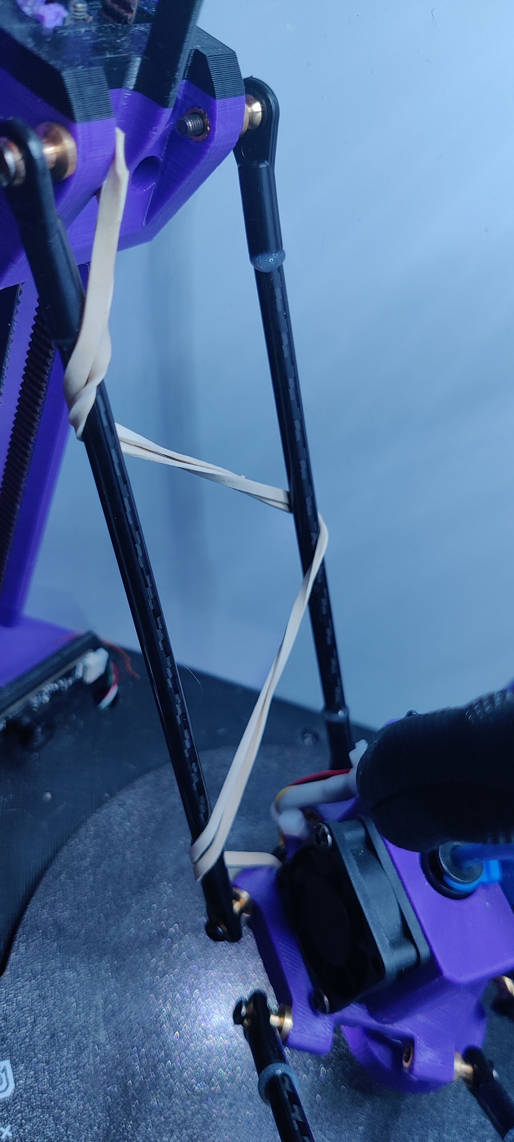
Attach the rubber bands on each arm as the picture, these take up the little bit of slop there is on the joints in the kit and makes sure print quality is premium.
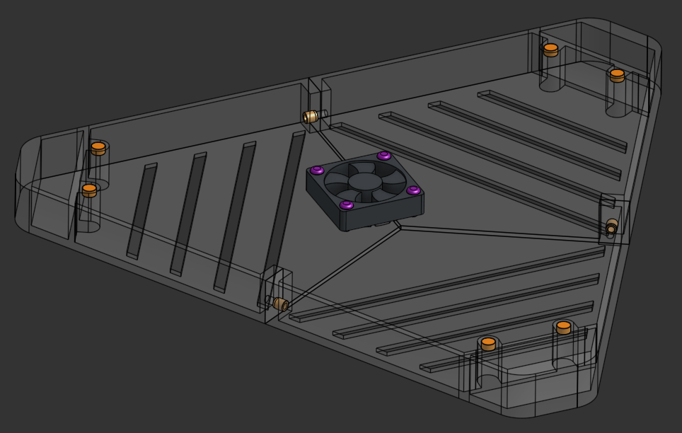
Prepare the top electronics cover by bolting it together using 3x M3x8 screws, attach the 4010 fan (sticker on the inside) with 4x M3x12 screws and gluing in the 6 magnets.
Now is also a good time to glue in the 6 magnets on the top frame, keeping polarization in mind.
⚠️ Important
Check magnet polarity before gluing to ensure proper attraction between cover and frame.
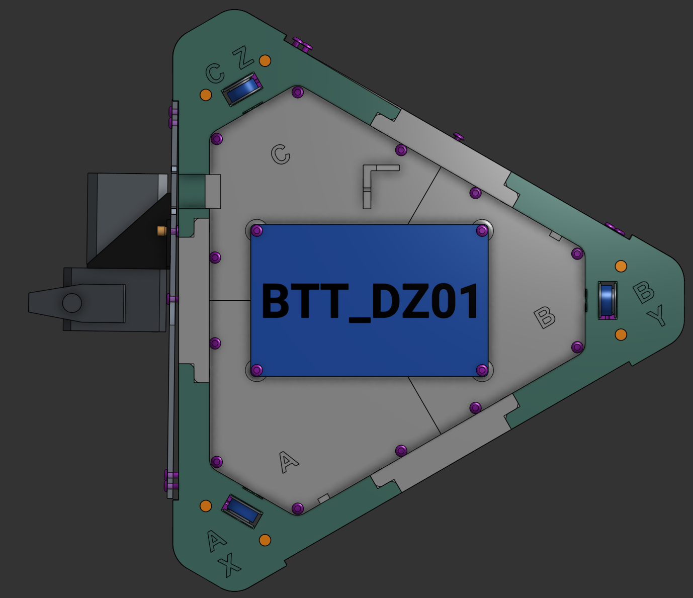
Install the BTT DZ01 board in the electronics bay using 4x M3x6 screws.
I recommend orienting it with the USB ports to the right, towards the "B" corner for easier access to the ports.
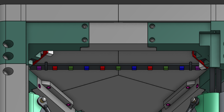
Install the RGB strip on the inside of the chamber using 2 zip ties on the top cover (labeled location).
Run the wire for the LED up to the BTT DZ01 trough one of the endstop-wire notches on the plate.
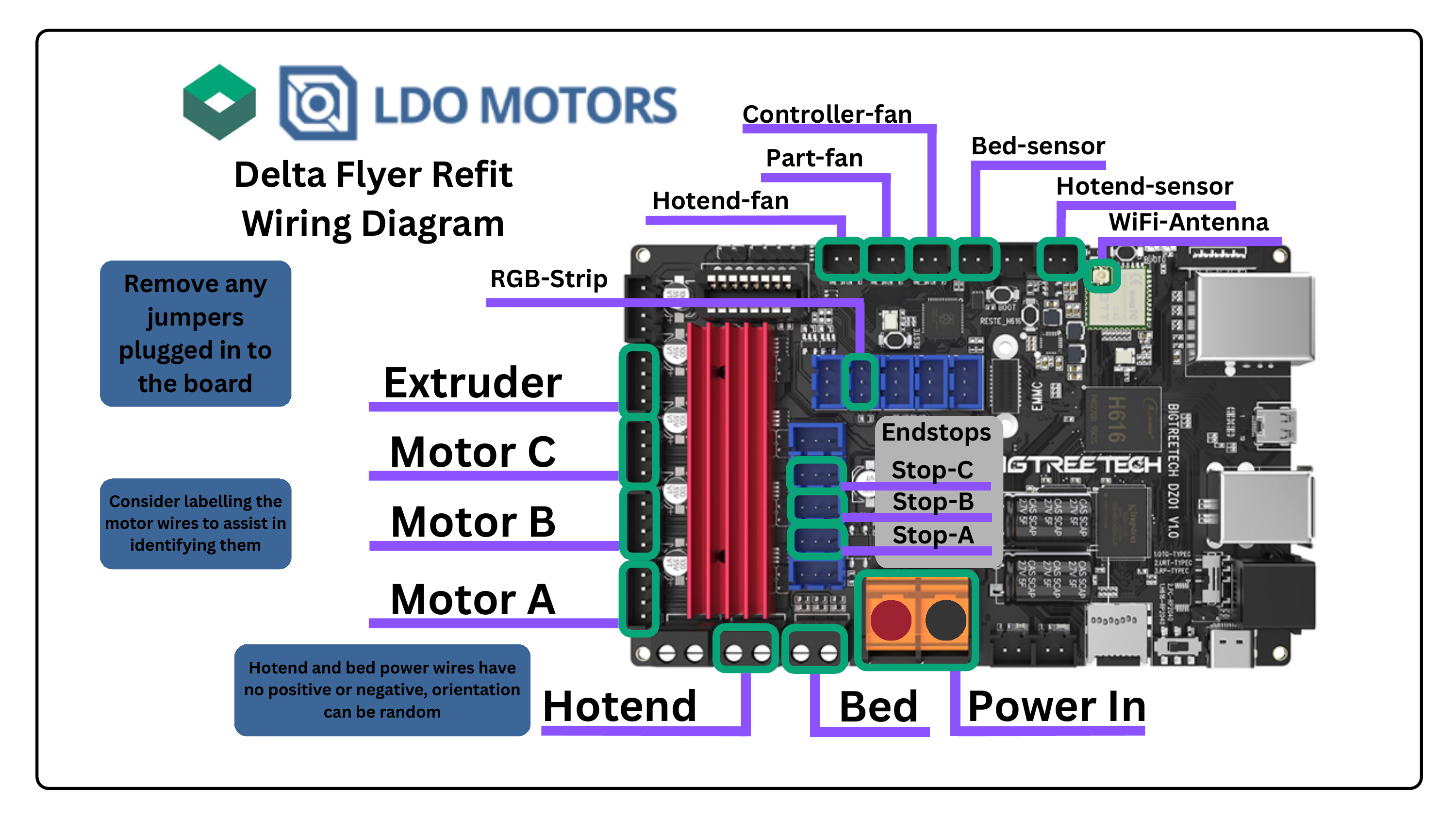
Connect all the wires according to the wiring diagram.
Install Klipper on the BTT DZ01 and run through the first setup process using the Klipper Installation Manual.
ℹ️ Reference
Refer to the separate Klipper tutorial for detailed software setup instructions.
After initial setup, install the 2 wire covers on the inside of the left panel using 8x M3x6 screws.
💡 Tip
Ensure wires are neatly routed before installing covers for a clean appearance.
Install the right panel with 6x M3x10 screws and finally the door, front right panel covers (4x M5x10) and door hinges using 2x M3x20 screws freely floating inside the hinge and the panel covers.
Use 4x M3x6 screws to attach the door to the hinges.
Also install the door handle with aM3x6 screw and glue in the 2 magnets for it.
⚠️ Important
Check magnet polarity before gluing to ensure the door closes and latches properly.
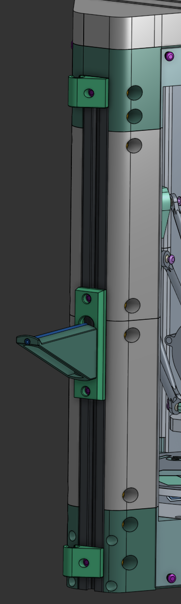
Attach the spool holder on the back using 2x M3x8 screws. Use some of the leftover PTFE tube in the spool holder arm.
You can attach the power cable hook using M3x8 screws too - one on the top, one on the bottom, facing to the right side of the printer.
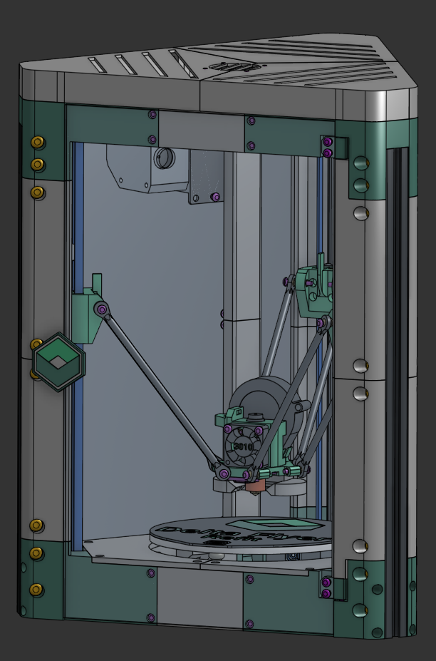
🎉 Complete!
Your Delta Flyer is now fully assembled and ready for printing!
After the build is complete, it might be a good idea to run trough the "Advanced Klipper Configuration" to ensure your prints are 100% accurate
ℹ️ What's Next?
Print! You can also have a look at some of the User Mods for the Delta Flyer if you want to change it up to suit your needs.
3. Recap & Conclusion
🎉 Achievement Complete!
Join Rolohaun DiscordAt this point, you have a printer you can enjoy, print what your heart desires!
Return to Delta Flyer Refit
Ready to explore more resources and configuration files?
← Back to Main Site